

State Machines
A finite state machine (FSM) is a mathematical model that describes a system with a finite number of states that transitions from one state to another based on the current state, the inputs, and a set of predetermined rules. A digital circuit that implements an FSM has memory, and its output does not depend solely on the current inputs.
A digital circuit that implements a state machine has the following characteristics:
- It has a finite set of possible states, stored in bistables.
- It has a set of input signals.
- The transitions between states are implemented with combinational logic and depend on the current state and the inputs.
- The clock signal coordinates the updating of the state.
There are two main models: Moore machine and Mealy machine.
Moore machine
In a Moore machine the output depends solely on the current state.
The behaviour of state machines can be visualised with a state diagram, which represents the machine's states, its inputs and its outputs.
In the state diagram of a Moore machine:
- The states are indicated by circles: E0, E1, E2…
- The arrows indicate transitions.
- The inputs appear on the arrows.
- The output is indicated inside the circle (State/Output).
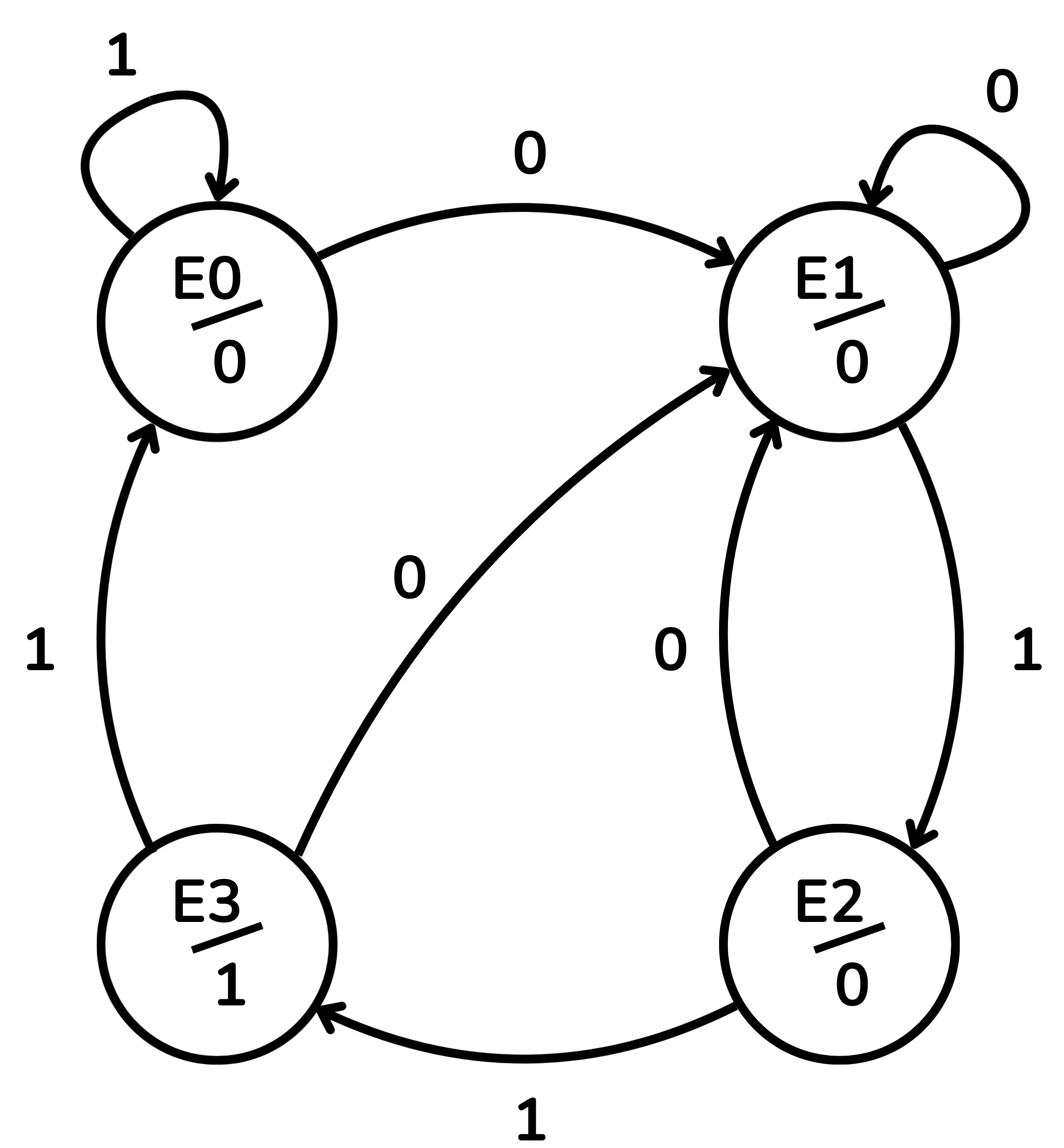
The following table will help us navigate this example of the state diagram. The first column represents the current state of the machine and its corresponding output. When the clock signal triggers a state change, the next state will depend on the input. If
| Current state/output | Next state | |
|---|---|---|
| Input=0 | Input=1 | |
| E0 / 0 | E1 | E0 |
| E1 / 0 | E1 | E2 |
| E2 / 0 | E1 | E3 |
| E3 / 1 | E1 | E0 |
Mealy machine
In a Mealy machine, the output depends on the current state and the current inputs. When the machine is in a given state, the output can change if the input changes, without waiting for the next state change. This can generate transient pulses between state changes.
Advantages:
- It often requires fewer states than a Moore machine.
- Fewer bistables and less combinational logic.
In the state diagram:
- The states are circles.
- The arrows indicate transitions.
- The arrow labels show input/output.
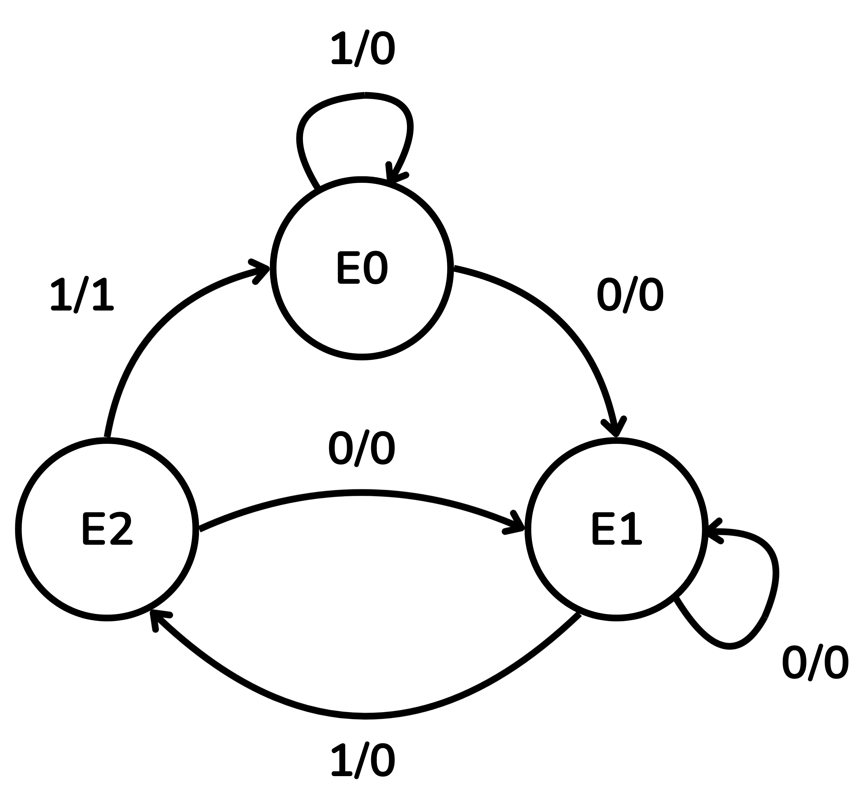
The table below will help us understand the state diagram. The first column represents the current state of the machine, its output will also depend on the input at that moment and is shown in the second and third columns. Only when the clock signal indicates will there be a change, which will take us to the state indicated in the fourth and fifth columns.
| Current state | Output | Next state | ||
|---|---|---|---|---|
| Input=0 | Input=1 | Input=0 | Input=1 | |
| E0 | 0 | 0 | E1 | E0 |
| E1 | 0 | 0 | E1 | E2 |
| E2 | 0 | 1 | E1 | E0 |
State machines are fundamental for designing logical components that need to follow a sequence or a protocol. They are used in:
- digital protocol controllers (SPI, I2C, UART),
- sequencers of complex operations (control units),
- pattern or sequence detectors,
- digital semaphores or control systems.
Example: Two-cycle delay line
This circuit reads a binary sequence and replicates it with a delay of two cycles. During the first two cycles, the output value is 0.
Take as an example the following initial sequence of numbers:
Output sequence (delayed by 2 cycles):
To realise the delay we use two D-type bistables in series:
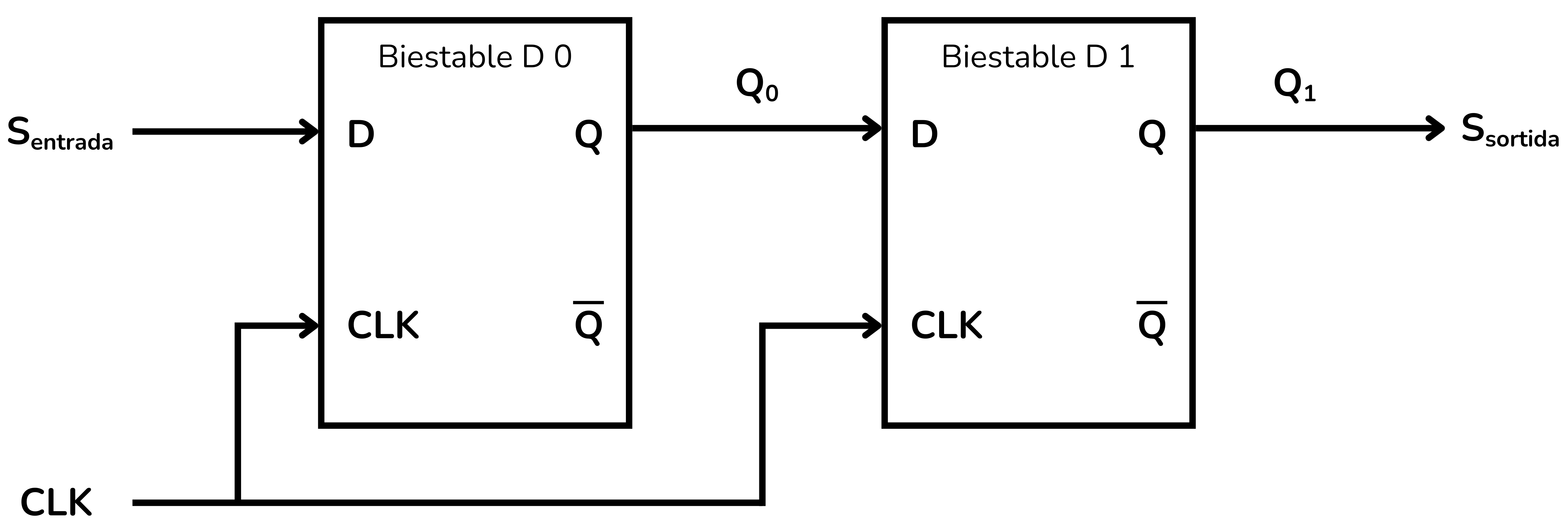
On each clock edge the following happens:
- The value held in bistable 1 is read as the output
. - The value held in bistable 0 (
) is moved to bistable 1 ( ). - The input
is copied to bistable 0.
This structure delays any input by two cycles.
Using two D-type bistables, the machine has
| Current State | [ |
|---|---|
| E0 | 00 |
| E1 | 01 |
| E2 | 10 |
| E3 | 11 |
The table below specifies the possible next states depending on the input
| Current state | Next state | |
|---|---|---|
| Sentrada=0 | Sentrada=1 | |
| 00 (E0) | 00 (E0) | 01 (E1) |
| 01 (E1) | 10 (E2) | 11 (E3) |
| 10 (E2) | 00 (E0) | 01 (E1) |
| 11 (E3) | 10 (E2) | 11 (E3) |
To this circuit we will add a reset signal
The complete state diagram is:
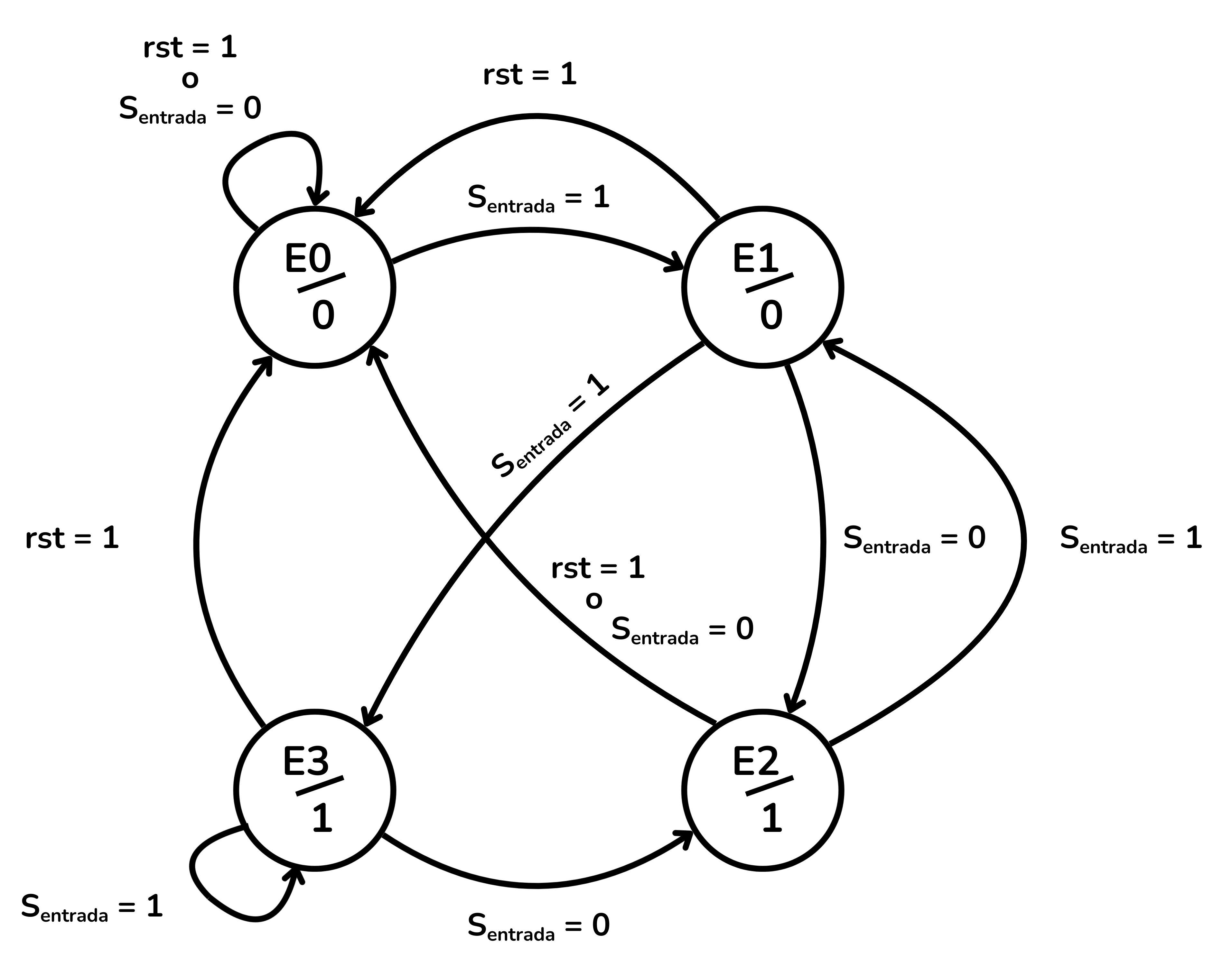
Since the output
Once the state diagram is complete, we move on to building the circuit in CircuitVerse. We connect the two D bistables in series sharing the same clock signal and the same reset signal (rst).
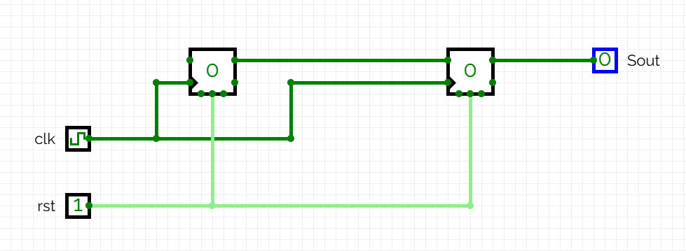
In the Judge’s exercises the reset signals are always synchronous, so we will do the same in this example, connecting the two bistables to the same synchronous reset.
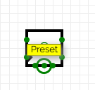
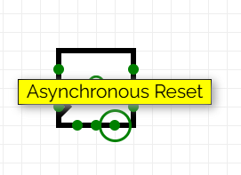
Thus the rst signal should be connected to the Preset input of the D bistable and not to the Asynchronous reset input.
To initialise the values, two multiplexers are added. The rst signal is the selector:
- The first multiplexer has as inputs the input signal
and a constant 0. Its output is connected to the input of the first bistable. - The second multiplexer has as inputs the output
of the first bistable and the same constant 0. Its output is connected to the input of the second bistable.
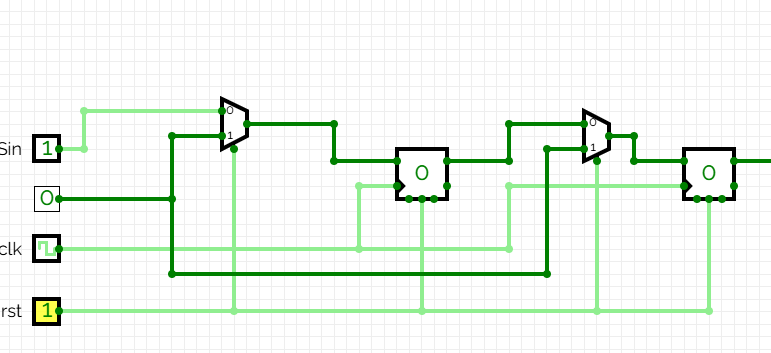
We will verify its operation with an initial example sequence:
With rst = 1, the bistables are at 0 (state E0) and
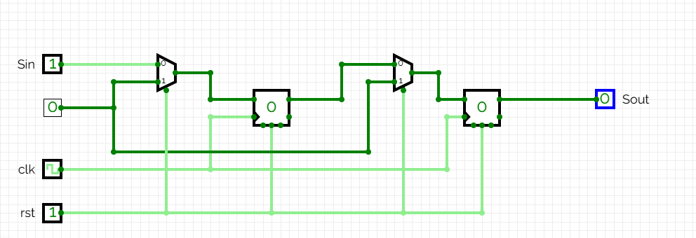
With rst=0, let the circuit evolve.
On the first clock edge the value of
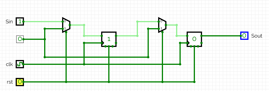
On the second clock edge, the value of
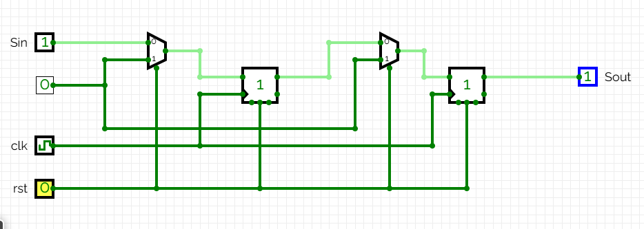
At this point in the process, the first value of
In these first two clock signals, the input and output sequences effectively implement a two-cycle delay:
Exercises on Jutge.org: Introduction to Digital Circuit Design
- Last two equal
- Delayed sequence
- Even number of 0's and 1's
- Circuit from state diagram
- Sequence 110
- Recognizing sequences
- Is it divisible by 3?
- Simple state machine
- Traffic-light controller
- Vending machine
Remember that to access the exercises and for Jutge to evaluate your solutions you must be enrolled in the course. You will find all instructions here.



Xavier Casas, Francesc Madrid
Lliçons.jutge.org
© Universitat Politècnica de Catalunya, 2026