

BCD Digits
In digital circuits, a number known as Binary-Coded Decimal (BCD) is a way to represent decimal digits using 4 bits. Each digit from 0 to 9 is converted into a fixed binary pattern.
| Decimal digit | BCD |
|---|---|
| 0 | 0000 |
| 1 | 0001 |
| 2 | 0010 |
| 3 | 0011 |
| 4 | 0100 |
| 5 | 0101 |
| 6 | 0110 |
| 7 | 0111 |
| 8 | 1000 |
| 9 | 1001 |
This encoding is widely used in numeric displays and calculators.
Example: Design of a circuit for a 7-segment display
We want to build a circuit that receives a BCD digit and lights the corresponding segments of a seven-segment display (common-cathode) to show it.
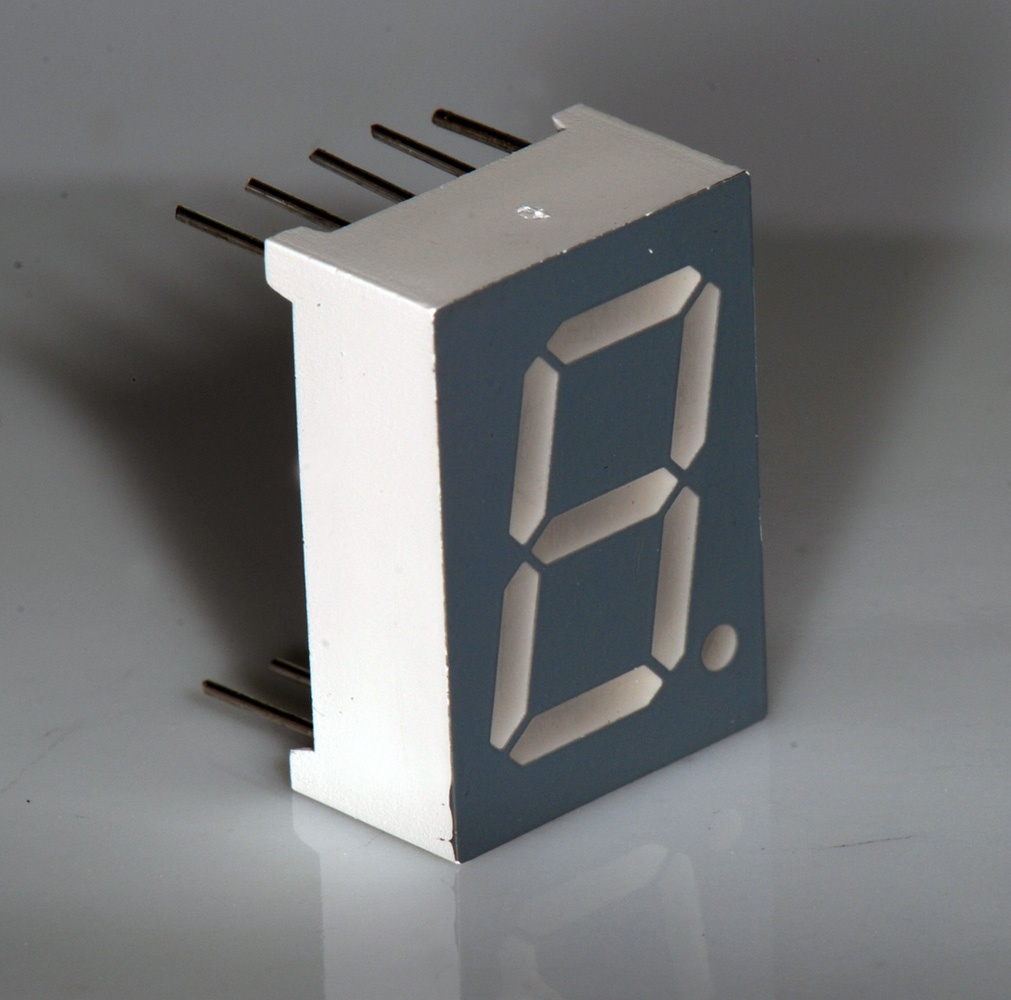
The following figure shows how the segments are named:
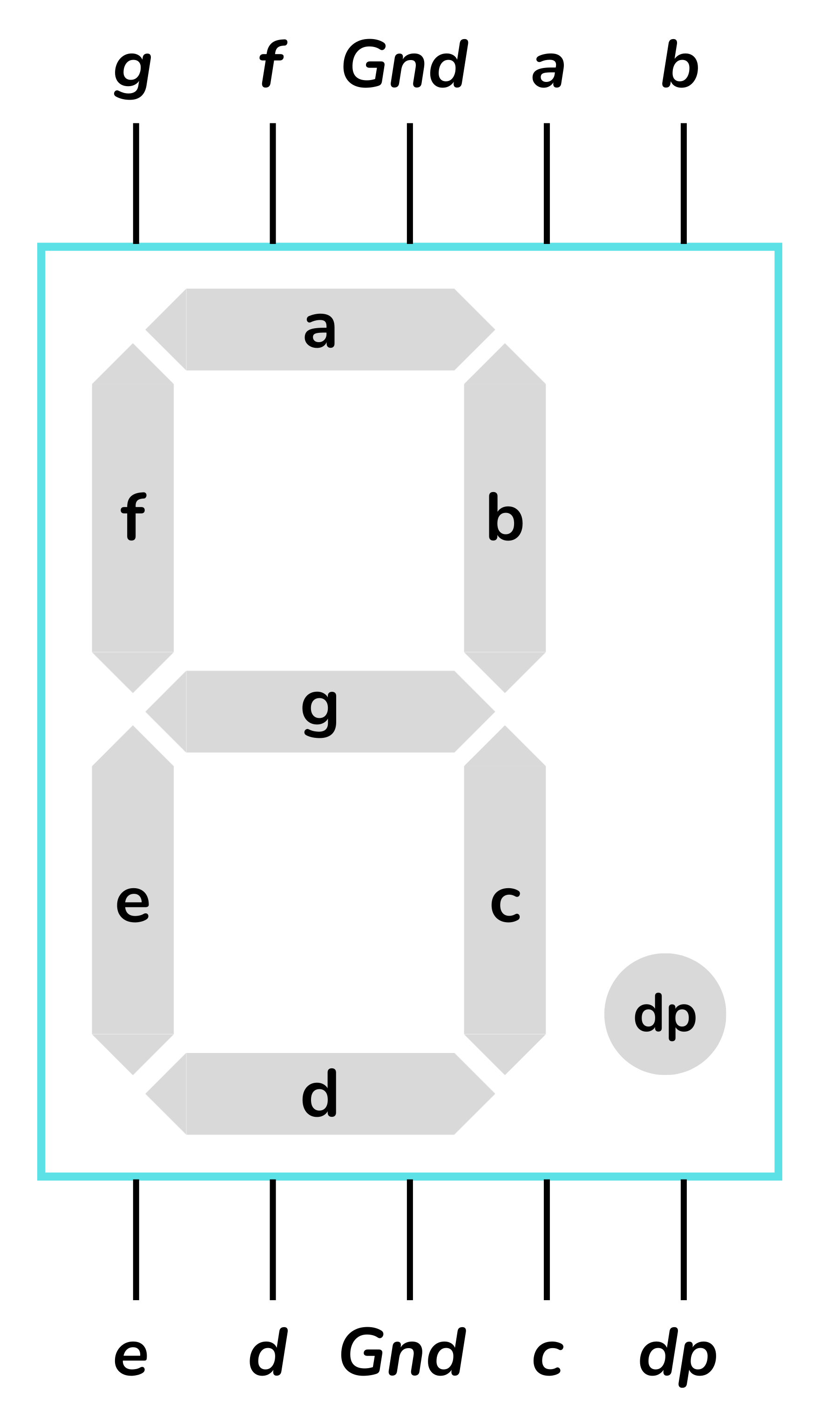
In the table below we indicate which segments should light up for each input decimal digit D[3:0]. A 1 means the segment is on; a 0, off.
| digit decimal | BCD | display | |||||||
|---|---|---|---|---|---|---|---|---|---|
| 0 | 0000 | 1 | 1 | 1 | 1 | 1 | 1 | 0 |  |
| 1 | 0001 | 0 | 1 | 1 | 0 | 0 | 0 | 0 |  |
| 2 | 0010 | 1 | 1 | 0 | 1 | 1 | 0 | 1 |  |
| 3 | 0011 | 1 | 1 | 1 | 1 | 0 | 0 | 1 |  |
| 4 | 0100 | 0 | 1 | 1 | 0 | 0 | 1 | 1 |  |
| 5 | 0101 | 1 | 0 | 1 | 1 | 0 | 1 | 1 |  |
| 6 | 0110 | 1 | 0 | 1 | 1 | 1 | 1 | 1 |  |
| 7 | 0111 | 1 | 1 | 1 | 0 | 0 | 0 | 0 |  |
| 8 | 1000 | 1 | 1 | 1 | 1 | 1 | 1 | 1 |  |
| 9 | 1001 | 1 | 1 | 1 | 1 | 0 | 1 | 1 |  |
| 10 don't care | 1010 | x | x | x | x | x | x | x | |
| 11 don't care | 1011 | x | x | x | x | x | x | x | |
| 12 don't care | 1100 | x | x | x | x | x | x | x | |
| 13 don't care | 1101 | x | x | x | x | x | x | x | |
| 14 don't care | 1110 | x | x | x | x | x | x | x | |
| 15 don't care | 1111 | x | x | x | x | x | x | x |
Don't-care Conditions
The 4 input bits can encode values from 0 to 15. However, a BCD digit only uses the values 0 to 9. The cases 10 to 15 are never shown and, therefore, are marked as x (Don't care).
When searching for groupings on the Karnaugh map, we can assign them the values that are most convenient to us in order to obtain simpler expressions.
Simplified Boolean expressions
A Karnaugh map must be created for each of the circuit outputs to obtain the Boolean expression for each segment.
Regarding the don't-care conditions, the value x=1 yields simpler equations.
The complete and detailed process can be found in several sources: Link 1, Link 2, Link 3
We obtain the following expressions for the segments:
Segment a:
Segment b:
Segment c:
Segment d:
Segment e:
Segment f:
Segment g:
These Boolean expressions allow implementing the circuit with AND, OR and NOT gates. The inputs are the bits
This type of decoder is very common in basic digital electronics.
Verification with examples
To ensure the formulas function correctly, we compute a few digits.
Example: digit 2
Expected results: segments a, b, d, e, g ON; c, f OFF.
Example: digit 4
Expected results: segments b, c, f, g ON.
Example: digit 9
Expected results: segments a, b, c, d, f, g ON.
Exercises at Jutge.org: Introduction to Digital Circuit Design
Remember that to access the exercises and for the Judge to evaluate your solutions you must be enrolled in the course. You will find all instructions here.



Xavier Casas, Francesc Madrid
Lliçons.jutge.org
© Universitat Politècnica de Catalunya, 2026