

Basic circuits
We begin with the most fundamental arithmetic digital circuits, such as half adders, full adders and bit comparators.
Example: Half Adder
The half adder (Half Adder in English) is the basis of full adders (Full Adders in English) and of n‑bit additions.
We will design a circuit that takes two bits, A and B, and computes:
- the Sum, and
- the Carry.
The truth table of the function we want to implement is the following:
| 0 | 0 | 0 | 0 |
| 0 | 1 | 1 | 0 |
| 1 | 0 | 1 | 0 |
| 1 | 1 | 0 | 1 |
When
We can use Karnaugh maps or the rules of Boolean Algebra to derive the two simplified Boolean expressions that describe the circuit's logic:
Thus, the circuit implementing this Half Adder is the following:

This circuit is one of the building blocks for full adders and for n‑bit adders.
Example: Full Adder
We will design a full adder that sums three input bits: the bits A and B plus an input carry bit
Its outputs are a sum bit, and an output carry bit
The truth table of the circuit is:
| 0 | 0 | 0 | 0 | 0 |
| 0 | 1 | 0 | 1 | 0 |
| 1 | 0 | 0 | 1 | 0 |
| 1 | 1 | 0 | 0 | 1 |
| 0 | 0 | 1 | 1 | 0 |
| 0 | 1 | 1 | 0 | 1 |
| 1 | 0 | 1 | 0 | 1 |
| 1 | 1 | 1 | 1 | 1 |
We can use Karnaugh maps or Boolean algebra rules to derive the two simplified Boolean expressions that describe the circuit's logic:
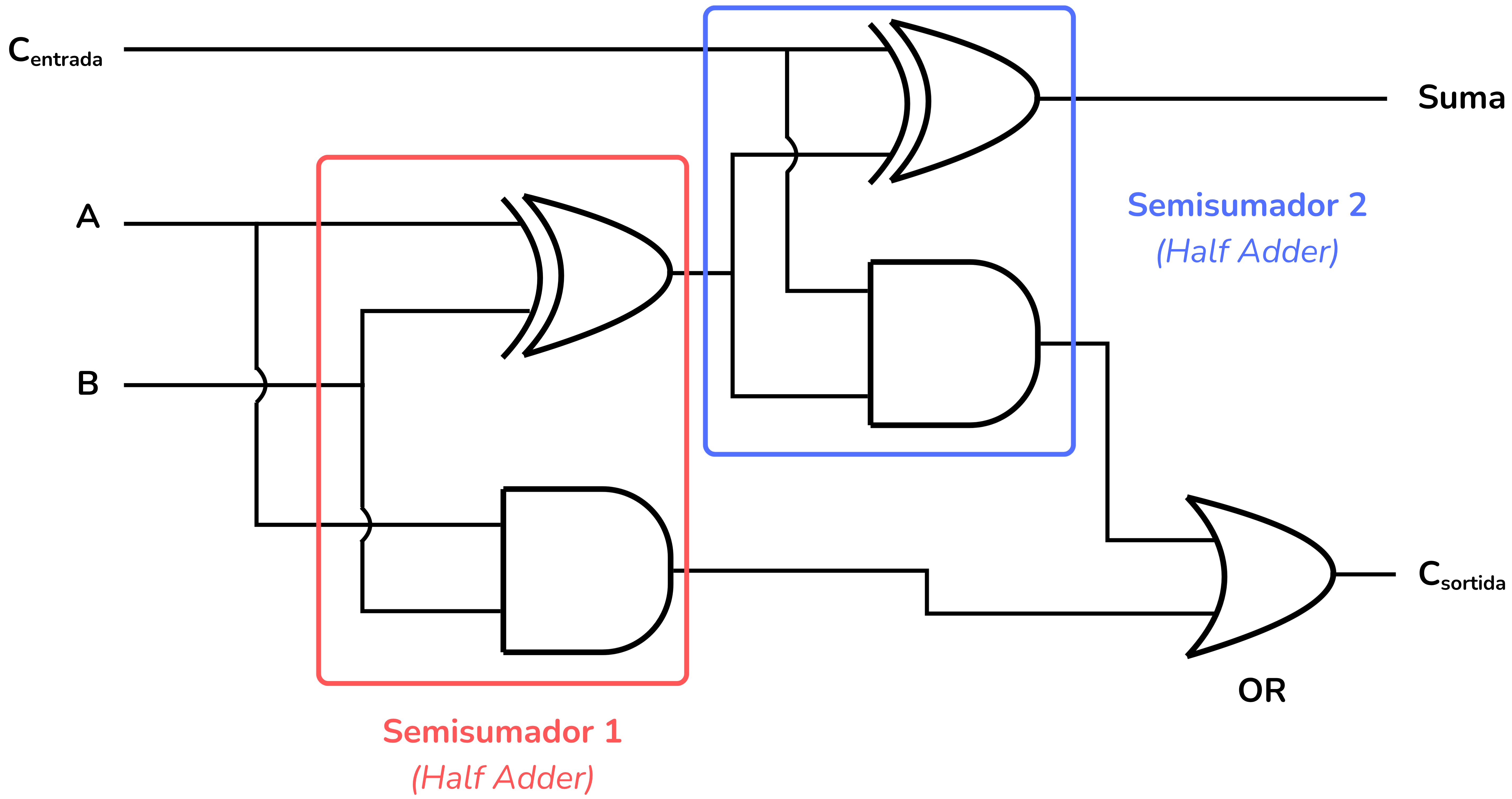
Thus, the circuit implementing a full adder is the following:

This circuit can be interpreted as two half adders with an OR gate for the output carry:
Example: Comparator
We will design a comparator circuit that takes two bits, A and B, and compares them.
Comparator circuits have 3 outputs: the first indicates if
The truth table is:
| 0 | 0 | 0 | 1 | 0 |
| 0 | 1 | 1 | 0 | 0 |
| 1 | 0 | 0 | 0 | 1 |
| 1 | 1 | 0 | 1 | 0 |
Simplified expressions:
Thus, the comparator circuit is the following:

Example: Multi-bit Adder
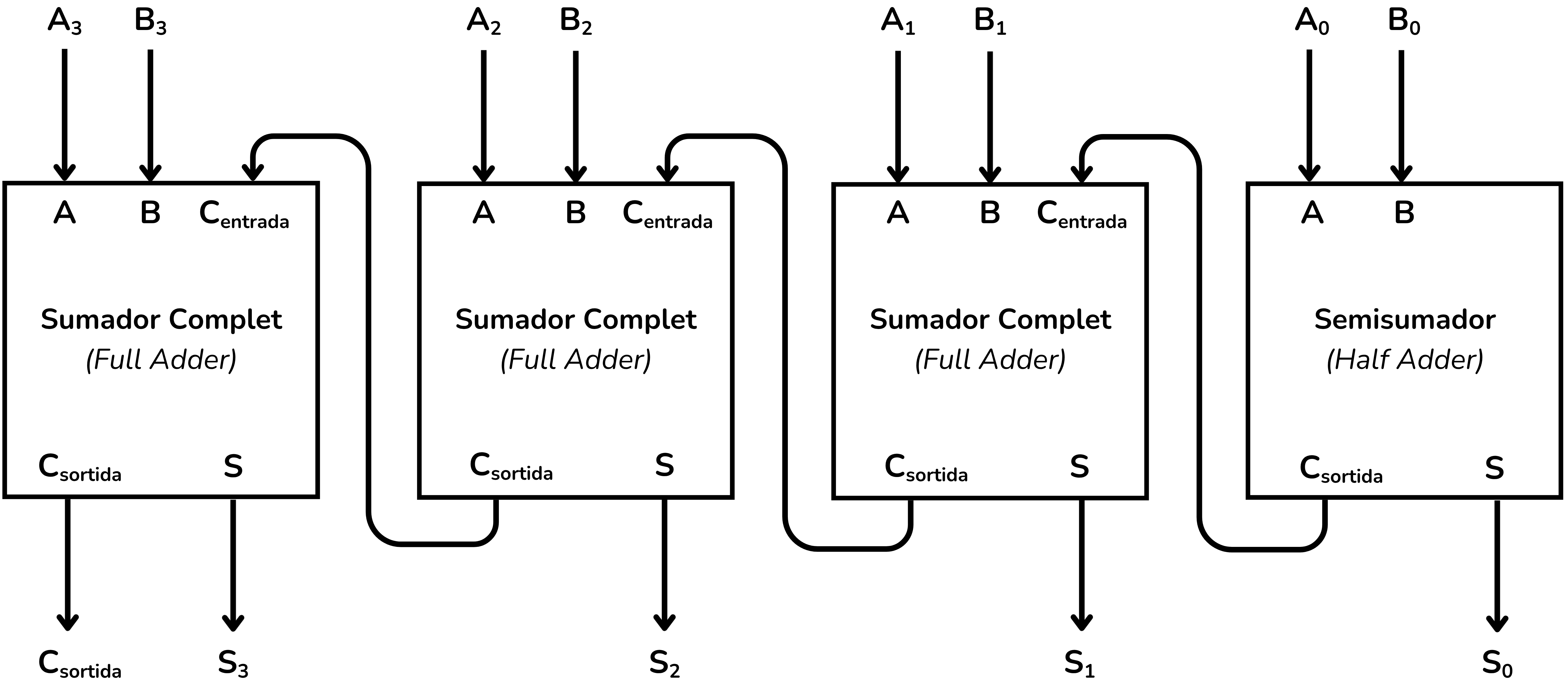
With the full adder and half adder you can build larger circuits, such as ripple-carry adders, which permit the addition of binary numbers with multiple bits.
For example, the following four‑bit adder:
Exercises on Jutge.org: Introduction to Digital Circuit Design
Note that to access the exercises and for the Jutge system to evaluate your solutions you must be enrolled in the course Introduction to Digital Circuit Design. You will find all the instructions here.



Xavier Casas, Francesc Madrid
Lliçons.jutge.org
© Universitat Politècnica de Catalunya, 2026