


4-bit Arithmetic
We will now discuss some arithmetic circuits that perform operations with 4 bits. We will see examples of 4-bit adders and subtractors and a very simple ALU (Arithmetic Logic Unit).
Example: 4-bit number addition
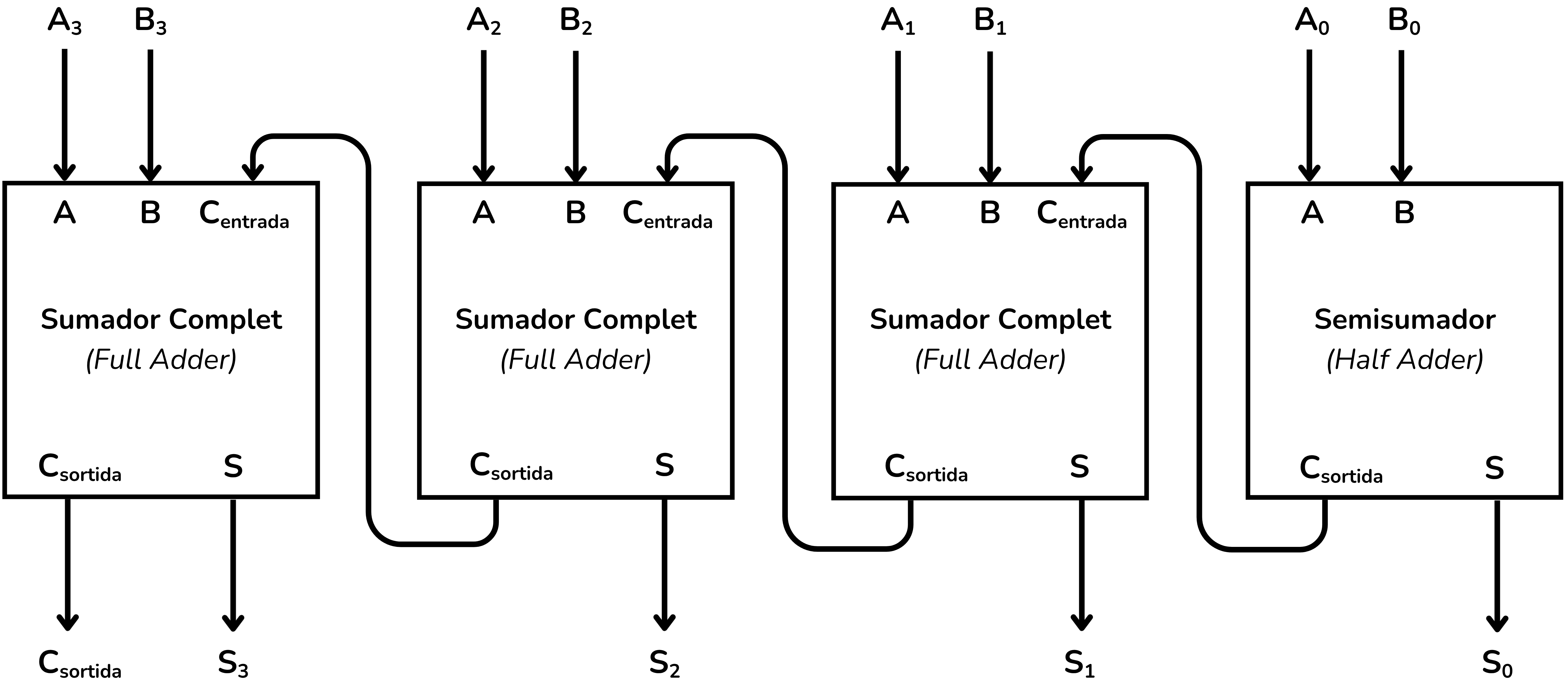
In this example we will see how we can add two 4-bit binary numbers. Binary adders (ripple-carry adders) can be built from full adders (full adders) and a half adder (half adder). Since we are dealing with a 4-bit addition, we will need to cascade 3 full adders and a half adder, or else 4 full adders if we configure the first full adder as a half adder.
CircuitVerse has an object named adder that implements an adder.
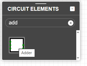
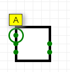
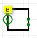
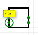
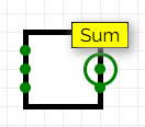
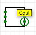
The inputs A and B are the operands being added and Cin is the input carry bit. The outputs are Sum with the result and Cout with the output carry. If you hover the mouse over the inputs and outputs of the object you can see its name.
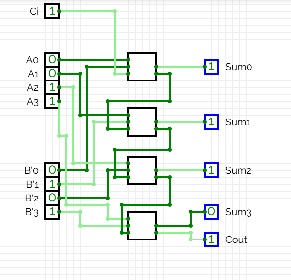
The circuit that performs the addition cascades 3 full adders and a half adder:
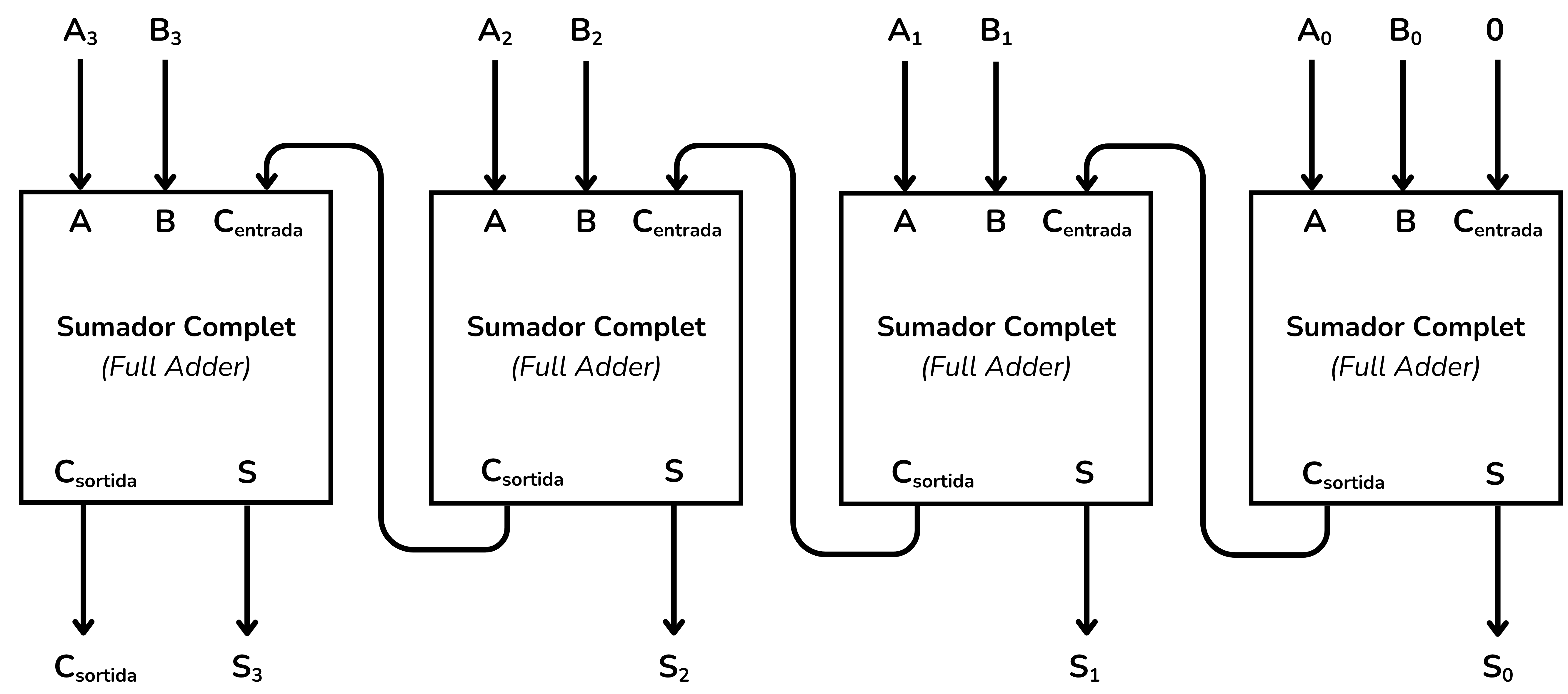
If convenient, we can implement the same circuit with 4 full adders. The function of the half adder can be performed by a full adder if we feed a constant
Implement it in CircuitVerse:
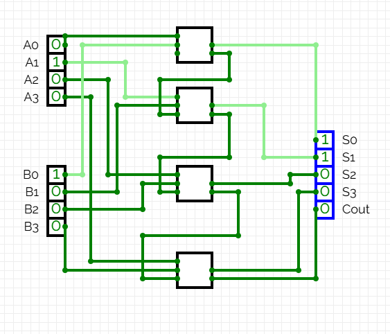
In this example the input values are:
- Input A = 0010
- Input B = 0001
And the outputs:
- Output S = A + B
- Output Cout = Carry-out
At Jutge.org, the 4-bit and n-bit algebra exercises use the bus notation

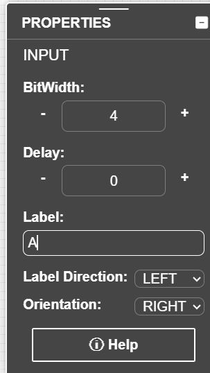
Once the BitWidth is set to 4 we can perform the addition with a single adder and simplify the circuit:
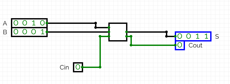
In CircuitVerse, the 4-bit inputs and outputs have black wires, while Cin and Cout, being only 1 bit, are green.
Example: 4-bit subtraction
To subtract two binary numbers we use the formula:
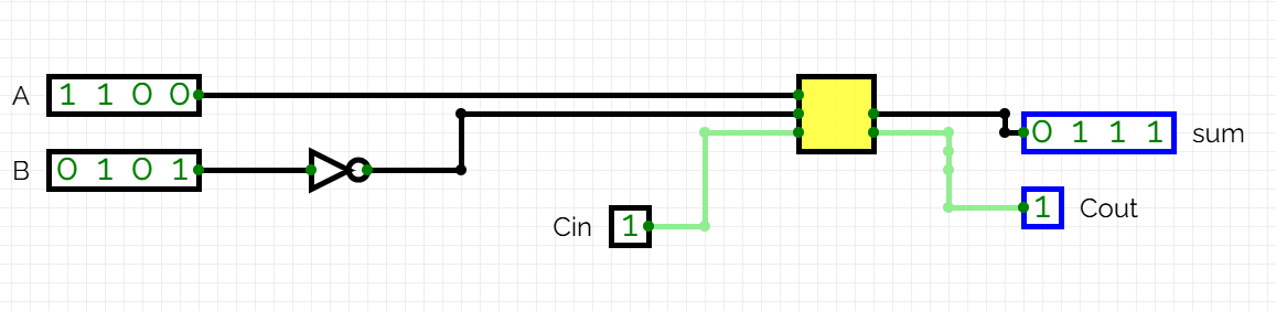
In this example we will perform a 4-bit subtraction. Consider:
- Input A = 1100 (12 in decimal)
- Input B = 0101 (5 in decimal)
- Output S = A - B (4 bits)
- Output Cout = Carry-out
First negate
Then perform the addition:
The following table specifies this operation bit by bit (it is not a truth table):
| bit | |||||
|---|---|---|---|---|---|
| 0 (LSB) | 0 | 0 | 1 | 1 | 0 |
| 1 | 0 | 1 | 0 | 1 | 0 |
| 2 | 1 | 0 | 0 | 1 | 0 |
| 3 (MSB) | 1 | 1 | 0 | 0 | 1 |
The circuit that performs the subtraction cascades 4 adders, with
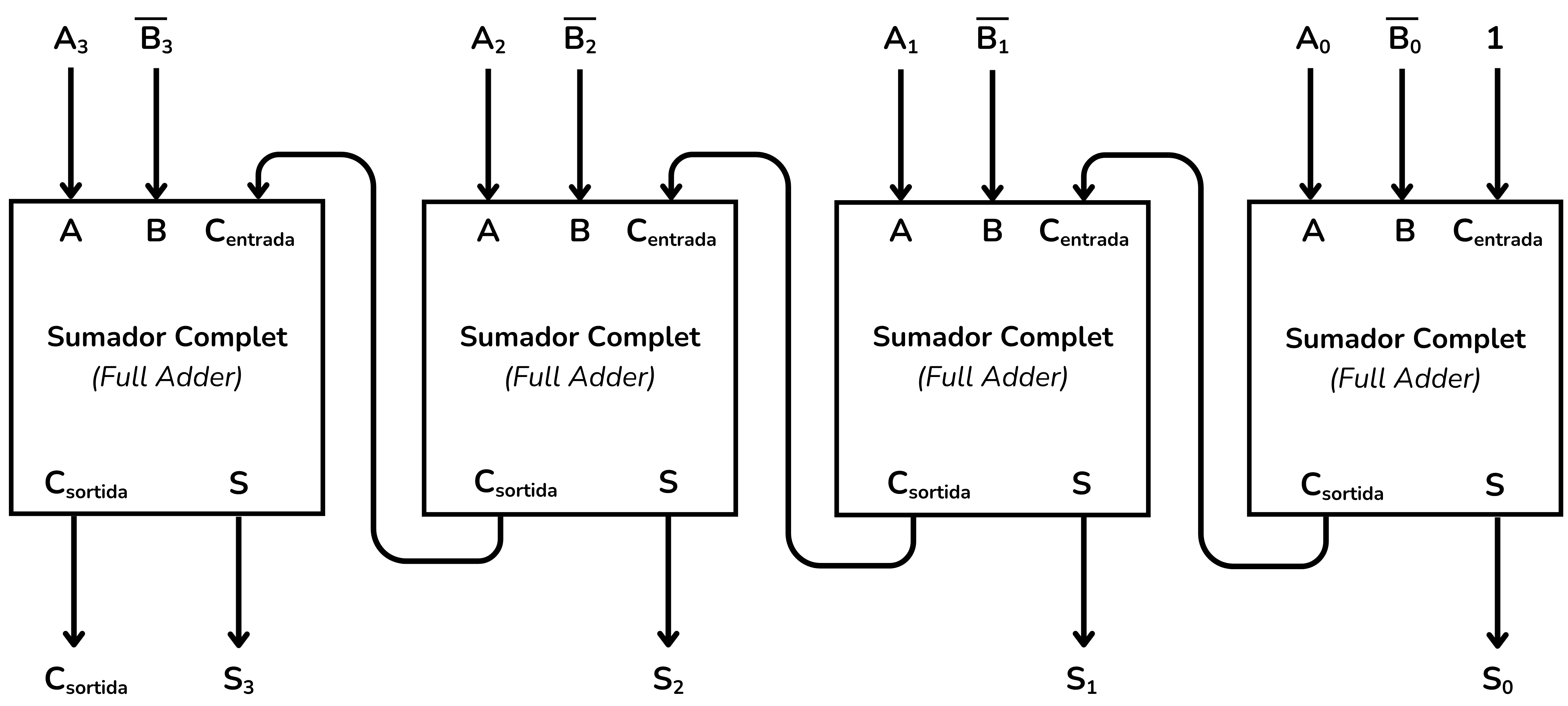
In CircuitVerse it is represented like this:
With BitWidth = 4 we can simplify the circuit:
Example: Selecting operations
Beyond performing arithmetic operations, arithmetic circuits can also implement operation selection. ALUs (Arithmetic Logic Units) allow choosing between operations based on a variable. This example explores this capability.
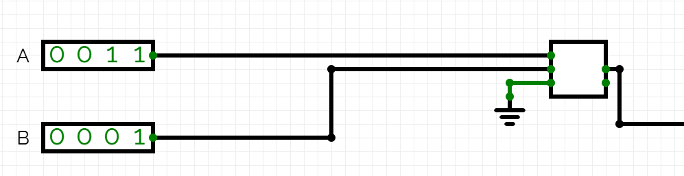
We want to implement a circuit that selects between a sum and a subtraction based on the input variable
- If
, a sum is performed. - If
, a subtraction is performed.
To perform the 4-bit addition
To perform the subtraction we will use:
To negate
Adding the circuit piece that performs the subtraction we obtain:
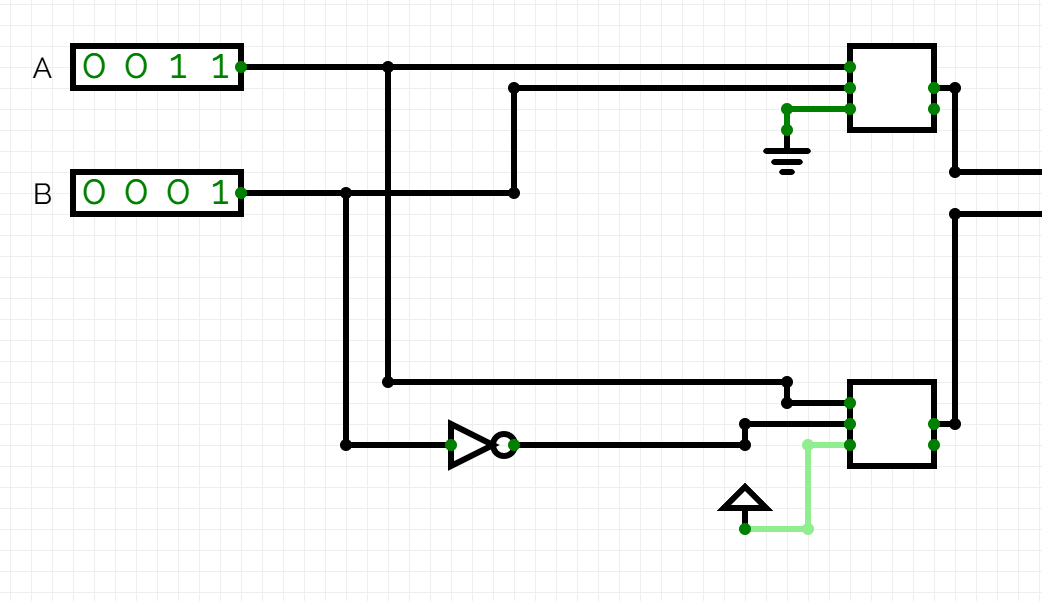
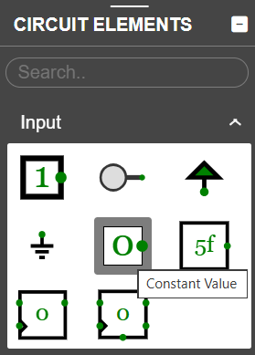
Both Power and Ground can be found in the CircuitVerse inputs menu. Both act as constants. Power always has the value 1 and Ground always has the value 0.
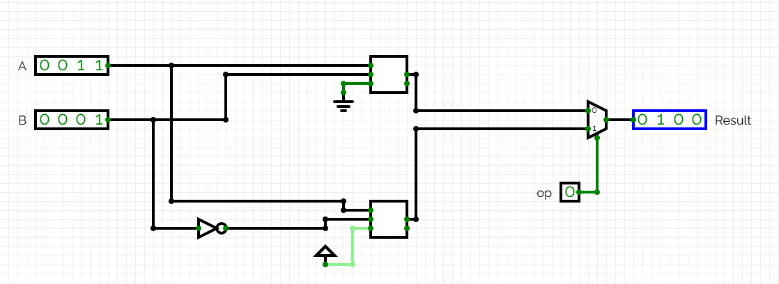
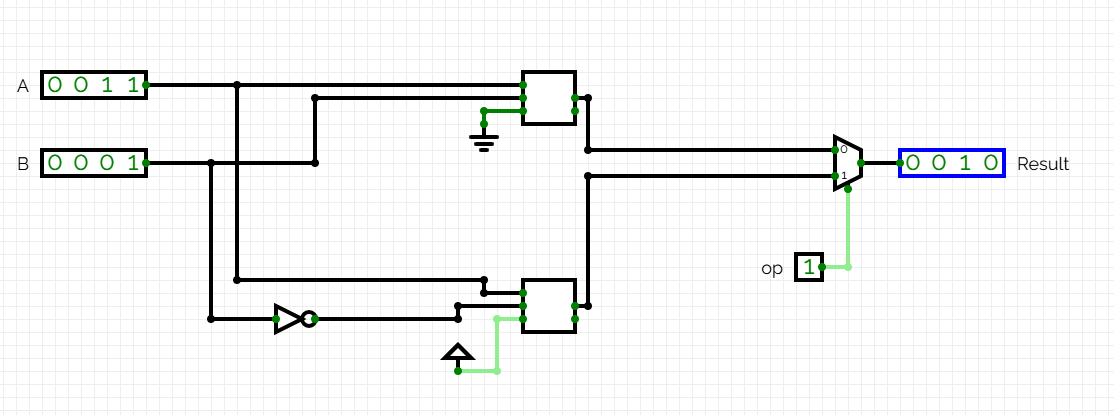
Now we need to add the part of the circuit capable of choosing between one operation and the other based on the input variable
The complete circuit, after adding this final element, is the following:
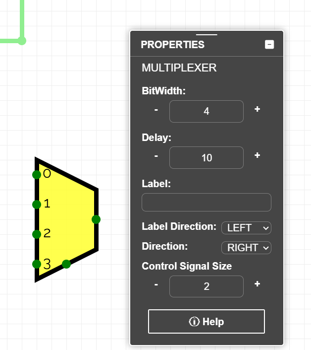
We can use a multiplexer with more than two inputs to handle more possible operations.
In the CircuitVerse properties menu you can modify the number of inputs with the control signal size property.
ALUs (ALU) typically select between 4 operations (4-input multiplexers) with a 2-bit selector
Exercises on Jutge.org: Introduction to Digital Circuit Design
Remember that to access the exercises and for Jutge to evaluate your solutions you must be enrolled in the course. You will find all instructions here.



Xavier Casas, Francesc Madrid
Lliçons.jutge.org
© Universitat Politècnica de Catalunya, 2026